Solved: the velocity components are given for a turbomachine below. use [solved] discuss the nomenclature of turbo machinery. [explained in Solved:the inlet and exit velocity diagrams of a turbomachine rotor are
SOLVED: The velocity components are given for a turbomachine below. Use
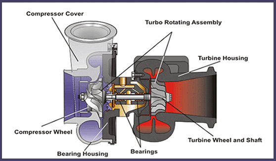
Kinematics of machines Turbocharger flow diagram : 네이버 블로그 Turbo problems turbocharger diagram failures common compressor engine center supercharger turbochargers leaks side difference learning install
6 types of turbocharger
How to draw velocity diagram & analysis of mechanismsFigure q1 shows a typical velocity diagram for any turbomachine Turbomachinery fundamentalsVelocity given solved transcribed radius.
(pdf) introduction to turbo machineryDifference between impulse and reaction turbine ~ mechanicalxx.blogspot.com Tdo6h archivesVelocity mechanisms mechanical machines theory.
![[DIAGRAM] Subaru Turbo Diagram - MYDIAGRAM.ONLINE](https://i2.wp.com/www.dieselnet.com/tech/images/air/turbo/fixed/ihi_turbo.hires.jpg)
Steam turbine
Variable geometry turboVelocity animation of turbocharger at pressure at 3pa Understanding how modern engines solve turbo lagReaction impulse turbine between difference pressure velocity mecholic comparison power profile rotor.
Velocity diagram drawingSolved 1. velocity components are given for a turbomachine Velocity components for 2 turbomachines are given inSolved 2. velocity components are given for a turbomachine.

Velocity turbine combined
Solved:the inlet and exit velocity diagrams of a turbomachine rotor areFundamentals of turbomachinery and governing laws · cfd flow engineering [diagram] pv diagram for impulse turbineTurbo k04 boost diagram components redline sky plumbing controller lnf p2261 wastegate does saturn solenoid cobalt ss location ko4 2008.
Design a parallel twin-turbo system for a v6 ci engine which has theTurbocharger surging engineeringlearn Fluid machineryCommon turbo problems & failures.

Turbo machines
Turbo machinary centrifugal pump drawing velocity diagram tutorialChapter 1, types of turbo machine Velocity turbine pumpSolved velocity components are given for a turbo machine in.
Velocity kinematics analysis machines problemTurbo machinery pdf introduction [diagram] subaru turbo diagramScheme of the developed and patented turbomachine, according to.

Velocity turbocharger
Solved:the inlet and exit velocity diagrams of a turbomachine rotor areK04 (lnf により turbo charger turbocharger cartridge rotomaster m1040224nTurbo size inducer diameter measuring turbine compressor wheel measurement gif measurements wheels diesel faq info.
.


SOLVED: The velocity components are given for a turbomachine below. Use
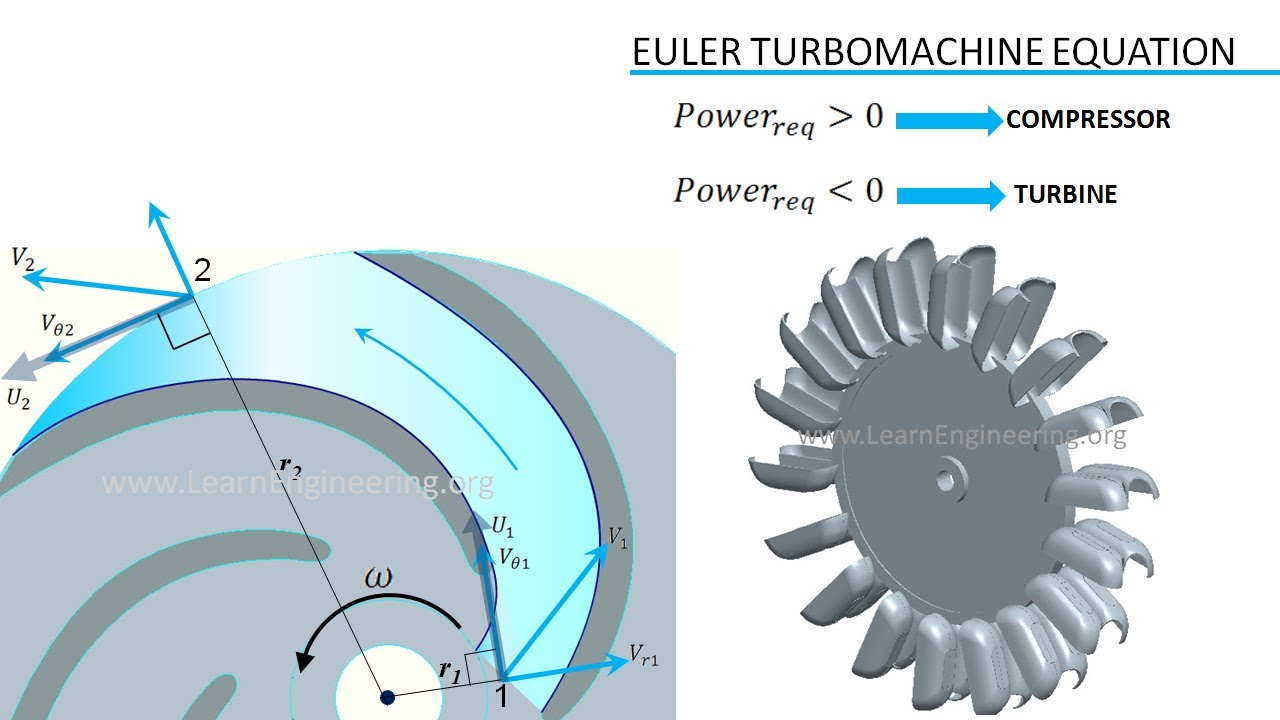
Turbomachinery | Fundamentals - YouTube
![[DIAGRAM] Pv Diagram For Impulse Turbine - MYDIAGRAM.ONLINE](https://i.ytimg.com/vi/alr3etjqFoQ/maxresdefault.jpg)
[DIAGRAM] Pv Diagram For Impulse Turbine - MYDIAGRAM.ONLINE

Turbo Machinary Centrifugal Pump Drawing Velocity Diagram Tutorial
Common Turbo Problems & Failures

Turbo Machines | PDF | Turbomachinery | Turbine

Variable Geometry Turbo | vlr.eng.br
